Demonstrating the Kobelco CK2750G Self Assembly Process
This section will cover the self erection assembly process for the Kobelco CK2750G. For this process, we’ll demonstrate assembling the machine by using the live mast to install the track frames, build the boom and install the boom assembly. We’ll also demonstrate using the counterweight installation system.
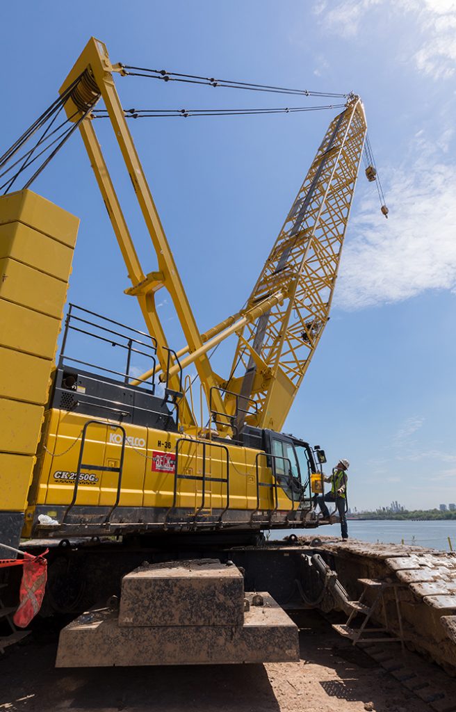
First fold the catwalks down and pin, then install handrails and secure them with the mounting bolts. The handrails are numbered for placement.
We’ll now place the LMI into the setup mode. This is done by pressing the icon on the LMI, showing the boom apart and holding it for 3 seconds. This will allow the boom hoist to operate as we raise the ganttry and mask up to the working position. Remove the anti two block cable for the mast from the upper frame and connect it to the receptacle in the junction box located in front of the upper frame marked Boom cable Two. The cable to operate the remote box for the ganttree and mast will now need to be connected to the receptacle on the right side of the machine.
Turn the power switch on the control box to the on position. Start the engine and set the speed to approximately one0 rpm. Move both ganttry cylinder control switches to the extend position to fully raise the gantry and install both gantry tension member locking pins. Lower the boomhoist wire rope as needed to keep some slack in the wire rope while the ganttry is rising. Use the switch on the same control box to raise the mast.
Push arms and push the mast up into the working position. Lower the boom hoist wire rope as needed to keep some slack in the wire rope while pushing the mast forward. After the mask, push arm cylinders are fully extended. Turn the key off in the control box and push the emergency kill button. Now start the crane from the cab.
It’ll be necessary at this point to programme the LMI into the self removal mode. First we’ll place the LMI into setup mode. This is done by pressing the icon on the LMI, showing the boom apart and holding it for 3 seconds. This will allow all functions to operate as we prepare the crane for selfassembly. At this point the LMI will automatically go into self removal mode.
We’re now able to lower the mast down to about 32 degrees. The LMI will stop the boom down operation. Push the icon on the LMI, showing the boom going down and hold it for 3 seconds. The mask will then continue lowering. At this point the out of angle warning will appear on the LMI.
When the mast angle reaches about minus nine degrees, the LMI will again stop the boom down operation. Now push the setup mode icon and hold it for 3 seconds. This will allow the boom down operation to continue. Secure the mast stand lock bars and install keeper pins. Lower the mast stands down onto wooden blocking.
Now fold up the top handrails. The mast assist arms must stay in the up position until the guy cables from the mast tip are connected to the working boom. We will now install the block to the mast. Use the rear drum to read the selfassembly block to the two centre masked sheets.
Install the anti two block weight and the limit switch to the mask tip. Secure the wire rope wedge into the wedge socket assembly and pin the wedge socket to the block location. Connect the antiwock cable ends. Pull the Antiw block limit switch by hand and cheque that the hook over hoist code on the LMI is eliminated. The block on the mast is now ready to be used to assemble the crane.
When the mast angle reaches its working radius of about 32 degrees, the LMI will have returned to self removal mode and all codes should be eliminated. We’ll now install the crawler frame assemblies onto the base machine. When installing the crawler frames, use the provided slings and shackles and attach them to the lifting eyes on the crawler frames. Run the slings from side to side, not from front to rear. Make sure to install the provided softeners to protect the lifting slings and trackpads, apply a coat of clean grease to mounting locations and pinhole locations.
The maximum working radius is 17ft from the centre rotation of the machine to the centre of the crawler frame. The tracks are directional, so it’s important that you cheque decals for front, rear, left and right side. A 360 degree swing is allowed before the first crawler frame is installed within a 17 foot radius. Position the crawler close to the frame. Remove the hydraulic hoses from the front and rear car body frame compartments, then connect the hoses to the quick disconnects on the track frames.
Turn off the engine and connect the control box to the receptacle on the rear centre of the crane car body. The control box is used for extending the main hydraulic track pins. This is the same control box used to control the translifter cylinders. Place the selector switch inside the cab to the translifter position. Start the engine and raise engine speed with the hand throttle to about 1000 rpm.
Cheque that both of the track mounting pins are fully retracted. Lift track frame and align the mounting brackets and pin locations.
The translator cylinders can be used as needed to lift the machine for more ground clearance or to level the machine in relation to the track frame. Turn off the engine using the control box to restart the engine fully insert the crawler connecting pins.
Insert the retaining pin and lock with the spring pin. Repeat the same process for the second track. Please remember that a 360 degree swing is not allowed after the first track is installed. Do not swing the centre point of the track frame past either of the trans lifters on the side. The track frame is to be installed.
Refer to the stability chart in the Operations and Maintenance manual for additional instructions. The hydraulic hoses for track mounting pins are common to the tracks. It may be necessary to bleed hydraulic pressure from the hydraulic lines to remove hoses. To do this, quickly, operate the control switch on the control box in the retract position to bleed pressure if needed. After the second track is installed, place the hoses back into the frame compartment, lower the machine to the ground and raise the translators cylinders.
Remove the floats and fold the translators into the transport position. Shut down the engine to remove the control box and power cord. Connect the hydraulic lines for the travel Motors from the crawler frame to the car body locations. All these lines are fitted with quick disconnect type connectors for fast and easy installation. Install the steps on the track frames.
We will now install the car body counter weights. First, remove the car bodily weight linkage locking pin. Lift the linkage on the car body weight up from the transport position and install the locking pins to hold linkage in the up position. Now install the top car body weight onto the counterweight base and connect them with the links. Lift the weight assembly and install it onto the carbody mounting bracket locations and secure it with locking pins.
This total weight of the car body assembly is approximately £30,200. The maximum working radius is 24ft from the centre rotation. Install the second car body counterweight assembly in the same manner. Place floats on storage location on the car body weights. We’re now ready to assemble the boom.
For this demonstration, we will build 90ft of main boom with the auxiliary sheet and install it on the machine as a onepiece assembly. First, lay out and pin the boom attachments needed on firm level ground. We’re now ready to install the boom base at this point. Do not install the two lower double taper boom base connecting pins. Unpin the boom backstops and raise them one at a time up to the working position.
Securing them with locking pins. Install the proper guy cables as needed for each particular boom combination. You’ll need to refer to the boom guideline arrangement chart, which is in the operator’s tab or the operation and maintenance manual. The guidelines have the ID stamped on the end at the pin location. We’re now ready to assemble the counterweight tray.
Set the counterweight tray on firm level ground. Install the lifting links to the counterweight tray, which is a onetime only process. Use suitable nylon straps to stack each of the 11,900 pound weights. Pin each of the counterweight sections together with the holding links. This assembly will consist of seven weights on each side of the counterweight base.
We’re now ready to install the counterweight assembly onto the rear of the machine. Start by setting the mast angle at about 45 degrees or less. Turn the ignition switch to the off position and connect the counterweight control box to the receptacle located on the right hand side of the machine.
Start the engine, raising the engine rpm to about 1000 rpm. Now you will lower the gantry.
Install the counterweight connecting cables onto the gantry brackets. Now we’ll position the rear of the machine over the counterweight assembly. Connect the cables on the gantry to the lifting brackets on the counterweight tray. Pull the retaining pins and using the extension bar tool, turn the mounting pins to the open position. Activate both left and right hand control switches to the up position and make adjustments as needed to keep the counterweight assembly level as it’s being lifted.
Stand clear of the counterweight assembly during this lifting procedure. After the counterweight assembly is completely raised, use the extension bar tool to insert the mounting pins and install the keeper pins. Disconnect the four lifting cables from the counterweight tray and fully raise the gantry to install the tension member locking pins. Place the extension bar tool into the mounting location on the counterweight tray. Turn off the engine and disconnect the control box from the receptacle.
We can now lower the mast and remove the load block from the mast. When the mast angle reaches about 32 degrees, push the boom down icon and hold it for 3 seconds. Lower the mask down and then set the LMI back into setup mode as before, disconnect the wedge socket and spool up the wire rope. Tie off the cable so it does not become loose on the drum. Remove the anti two block limit switch and connect the bypass plug to the end of the cable.
We are now ready to install the boom assembly. Install the rigging needed to lift the boom Assembly The rigging and shackles are provided with the machine. Follow the reeving diagrams shown in the operation and maintenance manual. Apply a coat of clean grease to the boom foot and bushings and mounting locations. Lift the boom base and travel forward as needed to align with the boom foot pins.
Set the three way switch inside the cab to the boom foot pin and move the hydraulic control lever to the extend position and install both boom foot pins. Install the locking pins and keeper pins. Install the shins as needed to take away any excess side play. Now shorten the rigging and move it forward to the next set of lifting lugs. As shown in the operation and maintenance manual, we’re now ready to raise the boom base and make the final connection.
Slowly raise the boom base to align the pinhole locations. Install the double taper type boom connecting pins. The double taper pins are used for a safer disassembly of the boom. Disconnect and remove the cables from the lifting lugs and make the final guy cable connection. It’s now safe to lower the mast assist arms.
Turn off the engine and disconnect the control box from the receptacle. Connect the cables from the angle, metre and anti two block system from the boom base to the machine. Secure the cables and leave enough slack in the cable to allow for booming up to 82 degrees without stretching the cable. We’re now ready to install load block and ball. Slowly raise the boom up just a few feet from the ground and secure the two bottom pins of the auxiliary sheave.
We will now connect the hoist cables out to the tip section. Use the front drum for the load block and the rear drum for the ball. For this demo, we will use four parts of line for the main block. For the load ball. Use the rear drum, which will use one part of line on the auxiliary shave.
First, install the anti two block weight. The Donut style weight is for the ball and the other weight is for the block. When mounting the wedge socket, follow the instructions on the decal located on the boom tip to ensure it is installed in the proper direction. Install the anti two block limit switch to the boom tip and on the auxiliary sheave. Run the anti two block cable from the cable reel to the tip and secure it to the boom mounting bracket.
Connect the wires for the Antiw system at the limit switches and complete the circuit by making the final connection at the reel. Secure loose cable using brackets before operating. Confirm that all guy cable Cotter pins are properly bent and all boom pins are installed and keeper pins are in place and make sure the boom is free of any pins, tools, or loose articles. Set up the LMI by first pressing the menu icon while the menu screen is displayed on the menu screen, select the setting with the Updown arrow icon.
The crane attachment screen appears.
The set of icons will need to be configured in this order. Select the crane icon.
Select the STD weight. Now select your configured boom length aux sheave. Next, select the main hook number one and press use. Then select the auxiliary hook number two. Press use.
The selection is the number parts of line screen. Next for the number one hook, touch the zero icon using the keypad. Enter the four parts of line. Next for the number two hook, touch the zero icon using the keypad, enter the one part of line and press the okay icon. The screen appears showing the selected items.
If these are verified, press the OK icon. After all the settings and input are complete, the screen returns to the crane configuration screen. The settings are displayed on the left part of the screen. It’s important that you cheque all your settings before continuing. Now, pull the limit switches for the ATB system on the main hook and on the load ball and confirm that the fault codes on the LMI are eliminated.
The outofangle should be the only code remaining. We’re now ready to boom the machine up into the working position after the machine has reached the working radius, all fault codes on the LMI should be eliminated. Double cheque to make sure that the anti two block is working on the main hook and also on the load ball. Also cheque that the high boom angle kickouts are working properly. In this configuration, the high boom angle should kick out at 82 degrees.
Now the machine is ready for operation.